
![]() Determining Loads on a Target Plate due to Explosive Detonation
Determining Loads on a Target Plate due to Explosive Detonation
PI: Prof. William Fourney
The Dynamics Effects Laboratory has equipment and instrumentation needed to evaluate materials at high strain rates. The lab has gas guns, Hopkinson Bars, high speed cameras, very fast responding instrumentation, and other equipment needed to investigate high loading rates. It has a federal and a state explosive license and is certified to conduct explosive testing. Strain rate testing capability is present for testing strain rates from 10 to the negative 2 up to 10 to the 6th power.
Lately we have been working with U. S. Army and U. S. Navy to develop computer codes that can be used to design the next generation armored personnel carriers. Very small tests are conducted with explosive charges, and measurements of impulse, velocity, and acceleration are made. If these tests are conducted very carefully, it has been shown that the results can be scaled to successfully predict results expected from charges of a very much larger size. In addition, in the development of computer codes, the accuracy of the predictions from the code should not depend upon charge size. Hence the codes should be able to predict the results of the small scale test just as easily as the result from full scale tests. The results from our testing are therefore used to ensure that correct mechanisms are being built into the codes.
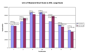
Figure 14 shows the results of small scale testing used to predict the measured impulse on a 28,000 pound target plate from the detonation of charges in the range of 5 to 10 pounds of TNT. These tests were conducted at ARL in Aberdeen, Maryland, on their VIMF (Vertical Impulse Measurement Facility).
In this series of tests the stand off distances for the targets ranged from zero (on the ground) to 16 inches and the depths of burial of the charges from 4 inches to 12 inches. The predictions were obtained from testing with charges no larger than 3.3 gm and the results, as can be observed from the figure below, were within 5 to 10 percent of the values obtained.
Complex angled bottom vehicle
(for larger image click here)
We have spent considerable time looking at how impulse varies with stand off distance and depth of burial and looking at vehicle shapes and their effects on impulse applied. As part of this investigation, we were interested in the mechanisms involved in the explosive delivering impulse to the plate. There were three main effects of the detonation to be considered, shock wave loading, air blast loading, and loading due to the ejecta from the crater. Our testing showed that shock wave loading can be important but only if the target plate is touching the soil surface. Air blast loading can also be important but only if the explosive charge is not buried. We found the main loading mechanism to be the very rapid moving ejecta (traveling at supersonic speeds) being brought to rest by the vehicle bottom. In the figure above, the impulse is greatest for the case of zero depth of burial and zero stand off distance. That is the target is on the ground and the explosive is not buried. For most cases the military is interested in vehicles which have ground clearance and for charges that are buried.
We have also looked at the vehicle shape and its effect on impulse. We have tested models with a simple angled bottom and also vehicles with multiple angles as shown in figure below. The results of these tests show that angle bottoms can be used effectively to lessen the loads felt due to explosive detonation.
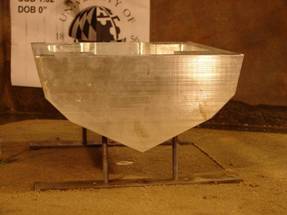
Complex angled bottom vehicle
We examined a wide range of stand off distances and depths of burial that we thought would be of interest to the military. The results obtained for the complex angled vehicle show that at a reasonable stand-off distance the impulse can be reduced to a value of about 1/3 of what would be expected with a flat bottom.
While knowing the impulse is advantageous, in order to fully design a vehicle for crew protection, one should also know pressures applied at various positions on the vehicle as well as stresses and accelerations. We have spent considerable efforts measuring pressures as a function of both time and position on the vehicles. For charges that are not deeply buried, the shape of the ejecta being thrown from the explosive site is quite irregular. If one takes a simplified view of the loading on the vehicles as a first order approximation, it could be viewed as the kinetic energy in the upward moving two-phase fluid being brought to rest when it strikes the vehicle. Since some of the soil is moving faster than other parts of the soil, then the pressure distribution on the bottom of the vehicle would not be expected to be smooth. This is what we have found in our pressure measurements. To overcome this problem we make 8 pressure measurements at any given distance from the center of the charge and a minimum, maximum, and average pressures are obtained. We have done a complete study of how pressures from the detonation of an explosive in saturated sand vary with stand-off distance for a given depth of burial and are currently investigating how changes in depth of burial at a given stand-off distance vary. The figure below shows typical pressure measured in these tests. These are the average pressures of those measured and show that after reaching a certain stand-off distance, an increase in stand-off distance does not reduce applied pressure by a significant amount.
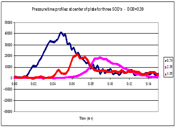
Pressure time profiles at the center of a plate at different stand-off distances
We have also been using digital image correlation (DIC) to determine other displacements and from these determine stresses, strains, and accelerations. We have on order some faster cameras that will permit better temporal resolution. The cameras that we now have are not fast enough to permit an accurate determination of stresses, strains, or accelerations. Once these cameras arrive, we will be using DIC to accurately determine accelerations. Until then we have been using magnetic velocity gages to determine accelerations. That is, the temporal resolution on the velocity is quite good and permits an accurate determination of acceleration. The figure below shows a simulated vehicle with one of our gages being used to determine velocities.
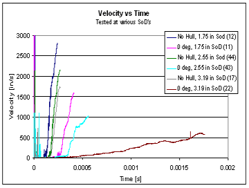
Velocity as a function of stand-off distance
For a flat hull the accelerations on a vehicle are very high. This figure shows velocities for a flat floorboard with and without a hull as a function of stand-off distance. Velocity does not need to be scaled but time, stand-off distance, and depth of burial do need to be scaled.
The slope of the curve gives an indication of the acceleration and the scaling factor from the 1 gm charge used, and a 5 pound TNT charge would be 13. Hence the time for the full-size charge would increase by 13 times that shown in the figure and acceleration would lessen from the values obtained directly from the graph by a factor of 13. The three stand-off distances shown are quite large for the full size charge. The stand-off distance of 1.75 equates to 23 inches in full scale, 2.55 equates to 33.5 inches, and the 3.19 equates to 42 inches for the 5 pound charge. At the very best situation (a flat hull with a stand-off distance of 42 inches, and a depth of burial of 4 inches), the lowest acceleration would be 292 g’s – quite high for a person to survive.
We are embarking on studies in conjunction with Doctors from the University of Maryland Medical School to investigate brain injury and limb amputation caused by buried mine detonation. While a lot has been accomplished in understanding the loading on vehicles due to buried mine detonation over the past two years, much remains to be done before computer codes are capable of designing the next generation of military personnel carriers that will provide for safety of the occupants who are subjected to buried mine detonations.
